| |
|
Click on
thumbnail to enlarge |
|
 |
| |
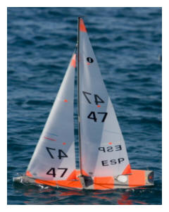
PIKANTO is the IOM that we have been making since early 2008. This example was used by Guillermo Beltri for the 2008 European championship dominated by light airs and which he won. It has the rc pot accessible at deck level aft of the mainsheet post which we designate Option 1. Nine of the top twelve boats at the 2008 European Championship were PIKANTOs or TOPIKOs either built by SAILSetc or built under licence from moulds supplied by SAILSetc.
The 2009 World Championship was won by Zvonko Jelacic using a PIKANTO. That event was dominated by stronger winds and six of the top nine boats were either PIKANTOs or TOPIKOs either built by SAILSetc or built under licence from moulds supplied by SAILSetc. The specification of our boats is available as a download under this section of the website. The specification of boats from the licenced builders will vary.
Photo by unknown |
popup size 49 kb |
|
|
 |
| |
PIKANTO is equally at
home in breezy conditions as this shot of Joan Conesa's
indicates. The hull form of PIKANTO is a minor development of
TOPIKO, winning design of the 2004 European championship. The
alterations were to add freeboard and flare forward and to add
emerging chines at the stern. Both changes were made to enhance
performance in stronger conditions, especially the gusty
conditions found on waters surrounded by trees and buildings
typical of many UK sailing waters.
Photo by Joan
Conesa |

popup size 86 kb |
|
|
 |
| |
The raised foredeck extends aft of the
mast position and supports the mast positively at boom height. A
self locking wheel adjustment allows precise mast rake control.
The headsail sheet emerges from the foredeck and leads stright
to the No 1 boom. For the No 2 and No 3 rigs the sheet is led
aft to a wire fairlead before going to the boom. The sheeting
system, whether using a Hitec servo and large drum or RMG280, is
contained entirely below deck. The main sheet and headsail sheet
each lead through a GRP moulded fairlead bonded to the inside of
the hull on the starboard side - just visible in this photo of
Pier Luigi Puthod's boat.
Photo by Pier Luigi Puthod |

popup size 49 kb
|
|
|
 |
| |
A shot of the same
boat showing a different view of the sheet installation. In fact
this is a TOPIKO and it is the Option 0 version having the rc
pot accessible below the deck ahead of the main sheet post. The
pot is offset to port while the winch and servo are offset to
starboard. The switch (not required for Option 1 boats) is
mounted on the vertical part of the bulkhead and the cable is
visible leading off to port and around the fin box/mast tube.
The main sheet exits the hull through a PTFE fairlead mounted
into the bulkhead near the switch from where it goes directly to
the main sheet post. The sheet line from the winch returns from
a block in the bow via a PTFE fairlead mounted on the port side
of the mast tube - just visible near the switch cable.
Photo by Pier Luigi Puthod |

popup size 119 kb
|
|
|
 |
| |
Some of the parts supplied with a hull moulding if the boat is to be completed from a kit. Although most of our customers tend to prefer us to do the completion work for them some have the time and like the task of putting the kit together themselves. We have good supporting material, plans and instructions to assist this.
Photo by
Sailsetc |

popup size 199 kb
|
|
|
 |
| |
Some of the parts used to complete a boat. The following photos
indicate how some of these are used.
Photo by
Sailsetc |

popup size 165 kb
|
|
|
 |
| |
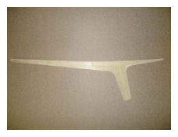
This is the moulding that is used to join the two halves of the foredeck along the centreline. It provides several other functions at the same time. The vertical part is, in fact, a 6 mm ID tube that is bonded to the bottom of the hull. A Dyneema line from the bottom of this tube provides the swivel for the No 1 headsail. Just aft of that tube is a recess which allows the attachment points for the N0o 2 and No 2 headsail swivels (ball raced version 120d) to be placed low down so the headsail boom is close to the deck. The depth of the main girder provides great stiffness and helps resist large rigging loads.
Photo by
Sailsetc |
popup size 177 kb
|
|
|
 |
| |
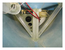
Looking aft from the bow towards the fin box and mast tube. On the left hand side is the moulded fairlead through which the sheet lines all pass. The diagonal connections between hull bottom next to the mast and deck edge under the shroud attachment points are specially moulded items.
Photo by
Sailsetc |
popup size 181 kb
|
|
|
 |
| |
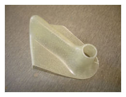
The moulded fairlead is shaped to bond properly to the hull/deck adge area. The return line back to the winch drum as well as the main sheet and the headsail sheet all pass through the hole. The moulded surface is smoothly shaped so the lines pass with minimal friction. For the Marblehead and Ten Rater the fairlead is made using carbon.
Photo by
Sailsetc |
popup size 185 kb
|
|
|
 |
| |
The moulded diagonals. These are made of glass and epoxy resin but we use carbon/epoxy versions for the Marblehead and Ten Rater hulls.
Photo by
Sailsetc |

popup size 202 kb
|
|
|
 |
| |
This shot shows the connection between the upper end of the moulded diagonal and the underside of the hull/deck flange on an IOM. The diagonal is bonded in place with a stainless steel plate embedded underneath that takes the screws holding the shroud attachment plate in place. The same method is used in the Marblehead and Ten Rater.
Photo by
Sailsetc
|

popup size 149 kb
|
|
|
 |
| |
The shroud attachment plates set flush with the deck. The plate is held down to the deck and connected directly to the diagonals with two M2 stainless steel bolts. The lower end of the rigging screw is a ball that is pushed through the larger part of the keyhole and then slid across to the other part (inboard side). Adding and removing the rig is a little quicker thanks to this refinement and, if you wish to adjust the shroud tension, you can do it without removing the rigging screw. The same method is used for the Marblehead and Ten Rater.
Photo by
Sailsetc |

popup size 91 kb
|
|
|
 |
| |
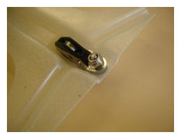
When using a drum winch it is useful to get the block round which the main sheet line turns right up in the bow. To do this we mount the block onto a special moulding that is bolted into the boat. Removal of the moulding then permits easy replacement of the block and/or line. We use a Hales block as these are stronger and have about half the friction of similar items giving a useful boost to winch power.
Photo by
Sailsetc |
popup size 114 kb
|
|
|
 |
| |
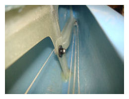
The moulding with the block is mounted in the bow and held in place with a bolt that goes through the tube through the foredeck down which the headsail swivel line passes.
Photo by
Sailsetc |
popup size 119 kb
|
|
|
 |
| |
This shot shows the mast gate area on an IOM. Our Marblehead and
Ten Rater are finished in a similar way. The mast gate supports
the mast positively transversely and fore and aft. The mast
adjuster screw bears onto the mast and provides rake control.
The threaded plastic housing into which it screws has an 'O'
ring in the end (just visible) that prevents the screw from
moving when not under load. The deck is marked to show where the
fore side of the mast should be for vertical. Each 3 mm aft from
here represents another degree of rake aft.
Photo by
Sailsetc |

popup size 131 kb
|
|
|
 |
| |
The top of the fin has a stainless steel insert bonded in place that takes the M4 stainless steel bolt used to hold the fin in place. Also visible at the head of the fin is the transverse screw that we use to align the fin correctly with the hull. This permits us to correct any discrepancy created by the fin box being bonded into the hull imperfectly.
Photo by
Sailsetc |

popup size 123 kb
|
|
|
 |
| |
Likewise at the bottom of the fin we use a stainless steel
insert through which M3 studding is placed. The fin is only
about 4.8 mm thick here so there is no chance of using anyhting
thicker than M3. The studding is bonded into the fin and the
ballast is held in place using the long nut with a slot to allow
tightening using a screwdriver.
Photo by
Sailsetc |

popup size 135 kb
|
|
|
 |
On some computer systems, Firewalls and settings in Browsers can prevent the small 'Pop Up' windows and text which are shown when the
 icon is clicked on or hovered over. This is down to each individual PC setup and outside of our control but you may be able to adjust your PC's settings so the 'Pop Up' windows become visible.
To download the drawings you will need Adobe Acrobat reader, which if you do not have, can be downloaded via the icon below.